News
Simulating Mechanical Stress on a Micro UAV Body Frame
We can all embrace the use of unmanned aerial vehicles (UAVs) as part of our society, especially with the recent stats showing that the sales of drones has tripled over the last few years, summing up to a market that is now worth more than $200 million.
A new paper highlights the potential use of drones – in particularly their maintenance actions – in order to properly maintain commercial drones in the industry. In it, the authors aim to provide quick guidelines and suggestions for effective maintenance of micro UAVs – based on a structure analysis and a simulation of the mechanical stresses on the UAV quadcopter body frames using a technique known as Finite Element Methods (FEM).
Aside from this, the paper also analyzes the results which highlight the weak aspects of the structure in order to predict possible failure mechanisms and as such, to “create effective maintenance approach for guaranteeing high level of product reliability and availability.”
Dividing the Quadcopter Movement in Four Different States
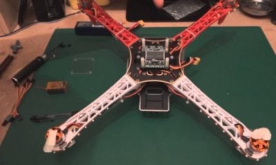
To begin with, the authors of this paper analyze the structure of a quadcopter with four arms and brushless electric motors that are positioned at the end of each arm. As such, they categorize the quadcopter movement in four different states:
- “by creating an equal rotational speed of the propellers on each motor the quadcopter generates enough lift force to move upward/downward (a);
- by increasing the rotational speed of the propellers on motors on the same diagonal, the quadcopter produces yaw motion (b);
- by increasing the rotational speed of the propellers on motors on the same side –front motors or rear motors- the quadcopter achieves pitch (c) and roll motion (d)”
They also investigate the possible maintenance actions that are suitable to maintain UAV systems and analyze the mechanical stresses acting during their flight – using specific FEM methods in order to create the reliable maintenance approach for a safe and available machine.
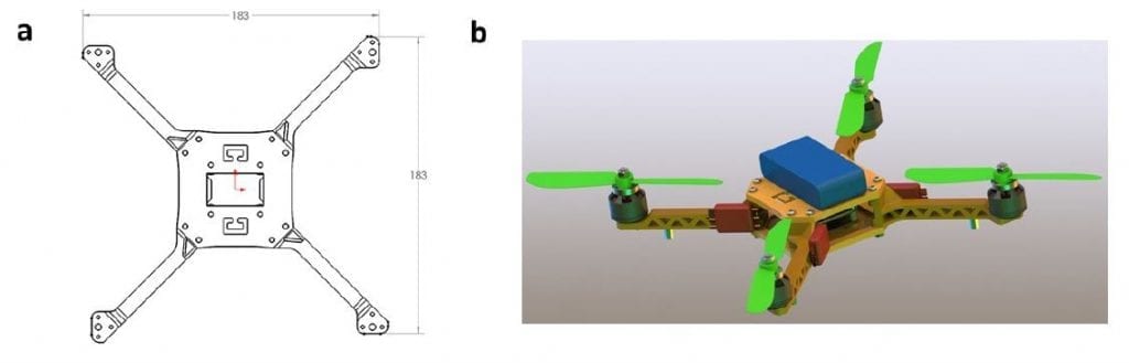
Geometrical shape (a) and 3D rendering (b) of the UAV.
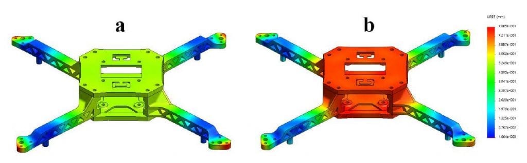
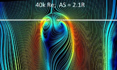
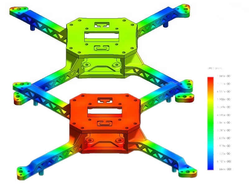
Simulation results for landing: (a) displacements for ABS plus plastic (Max 3,2 mm); (b) displacements for carbon fiber (Max 6,5
mm).
FEM Simulations Through the Use of Variables
Through the use of variables such as mesh type, jacobian points, element size, total nodes, total elements, maximum aspect ratio and others, the authors divided the quadcopters in categories and performed the simulations.
Based on the results, they highlighted that the highest stresses in landing mode occur on the arms near to the frame center.
“These considerations lead to agree that there is a consistent difference between usage of carbon fiber and ABS plus plastic during hard landing events in terms of mechanical strength. Due to its mechanical properties, carbon fiber is a stronger material with a high Young modulus, which is generating lower elastic strain and fragile behavior beyond the tensile strength. On the other hand, ABS plus plastic has higher tensile strength, which can reduce probability of sudden cracks in a collision with rigid surfaces during emergency landing.”
The presented results show that continuous maintenance and special monitoring actions should be taken into account by micro UAV users and operators in order to check after every landing on a rigid surface bolt and connectors between the frame and arms – as well as to design or equip rubber nozzles or shock absorption devices on the landing gears to reduce stresses and vibrations from the ground.
Conclusion
“Using SolidWorks Simulation Tools and Abacus for FEM analysis, an estimation of the mechanical stresses generated by impacts on simple quadcopter frame has been studied. The analysis was conducted for two types of materials: carbon fiber and ABS plus plastic. Von Mises stresses on quadcopter arms have been highlighted. Those stresses represent a critical factor (in relation with tensile strength of ABS plus plastic and carbon fiber 3D printing material) creating possible plastic deformations and cracks in case of drop landing on rigid surface. The study finally gave suggestions for correcting checking and maintaining the quadcopter frame,” the authors pointed.
As they believe, further research is necessary in order to move from a simulation contest to a real condition monitoring system for micro UAVs – with the main aim to prove the results obtained with the FEM analysis.
Citation: Alberto Martinetti, Mihran Margaryan, Leo van Dongen, “Simulating mechanical stress on a micro Unmanned Aerial Vehicle (UAV) body frame for selecting maintenance actions”,
Procedia Manufacturing, Volume 16, 2018, Pages 61-66, ISSN 2351-9789, https://doi.org/10.1016/j.promfg.2018.10.160. (http://www.sciencedirect.com/science/article/pii/S2351978918312812)