News
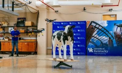
A Quadcopter Flying Robot: Design and Experimental Research
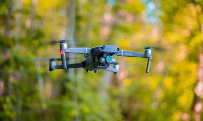
In today’s era, there are many commercially available remote controlled flying toys – known as drones or unmanned aerial vehicles (UAVs). In what’s a growing technology, drones like these must have autonomous flight functions implemented, mainly to prevent accidents and help users safely land them without any obstructions.
However, according to analysts, one of the most important advantages of this type is the ability to maintain a certain position in space. In a paper, a group of researchers examines the quadcopter flying robot – and particularly its function to contribute to a sustainable development in the search for new energy sources, preferably coming from renewable use of technology such as biomass.
The main aim of this paper is to build a system that would allow for “taking photos from the air or inspecting hard-to-reach places” and use in environmental protection purposes as well as air pollution monitoring.
Designing the Mechanical Part of the System
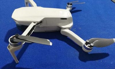
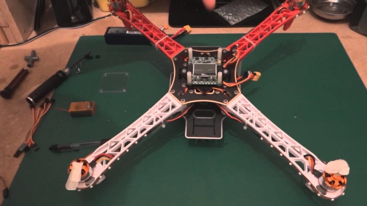
The researchers and authors of the paper take a popular TAROT FY-450 frame with a standard configuration to build a new robot and its mechanical structure – giving it the multirotor pack known as the EMAX MT2213 which is characterized by precise machining and hub-free mounting of propellers.
The weight of the motor (including the nut and propeller) is 70 grams and the motors are controlled by the classic FastPWN 30A ESC with SimonK multirotor firmware – as well as a LiPo 3S1P battery with a 2200 mAh capacity and weight of 160g.
The total weight of the drone including the flight controller is approximately 1350g.
Designing the Electronic Part of the System
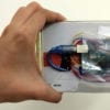
When it comes to the electronics inside this drone, the authors are using the ARM LPC4088 microcontroller from NXP with the Cortex-M4 core clocked at 120MHz as the main part of the control unit.
The additional parts include inertial sensors (MPU9250 IMU’s from InvenSense) each packed with a 3-axis gyroscope, a 3-axis accelerometer and a 3-axis magnetometer. In addition to this, the entire control unit is equipped with a micro-USB connector and a color OLED display, joystick and two additional buttons.
Designing the Informatic Part of the System
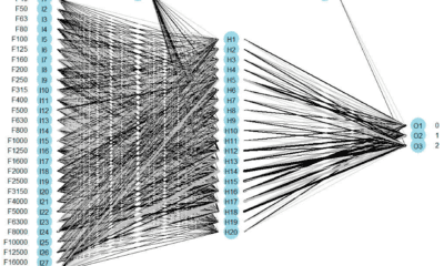
According to the authors, the software part of this system consists of several prepared programs, entirely prepared in the C language. The software is divided into two microcontrollers and an additional core due to the specificity of the operation.
In the verification tests, there were several successive stages.
“The first stage was the verification of the operation of used filters in Matlab, using the registered measurement data. This made it possible to verify the correct operation of all used measuring sensors, control equipment and the selection of optimal filter parameters. The orientation of the measuring axes of all the sensors used was also set and checked. After this stage, all the measuring sensors and engine speed controllers used were calibrated.
The next stage was to analyze the black box on the drone, after implementing the filters and regulators. In this way, the operation of the implemented automatic control systems was verified, comparing the obtained results to a model created in parallel in the Simulink engineering environment.
The final stage was field tests. Based on them, the correct operation of regulators and filters during real flight tests was checked, which allowed to assess what further modifications will be needed to increase the stability of the platform, as well as enable more precise selection of controller parameters. During field tests, the data processing efficiency on the control unit was also verified. ”
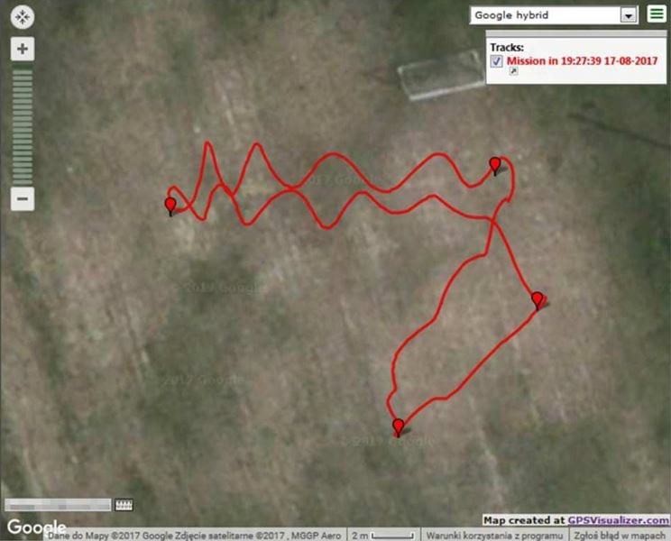
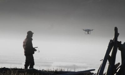
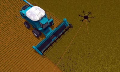
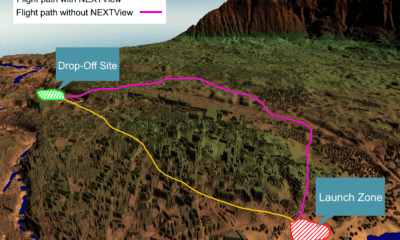
A travelled path by the robot in navigation mode – map
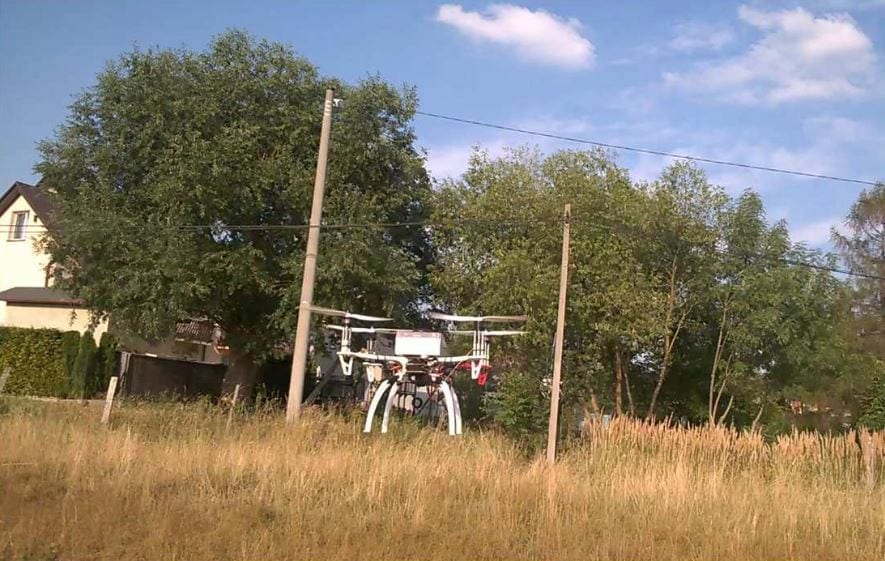
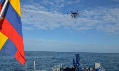
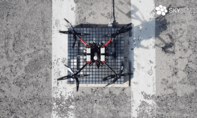
Robot during operation in navigation mode – a trip from point to point
Final Results
In the end, the quadcopter designed by these authors showed massive advancements for testing and cutting processes, built at the Institute of Mechanical Engineering at Warsaw University of Technology in Płock. The main finding was that this system gives massive possibilities to conduct a wide range of tests for variable construction and working parameters as well as variable parameters of the plants itself.
Citation: Design and experimental research of a quadrocopter flying robot, Grzegorz Suchanek, Wojciech Ciesielka, E3S Web Conf. 46 00012 (2018)
DOI: 10.1051/e3sconf/20184600012, https://www.e3s-conferences.org/articles/e3sconf/abs/2018/21/e3sconf_enos2018_00012/e3sconf_enos2018_00012.html