News
Addressing Magnetic Interference in Electric Fixed-Wing Unmanned Aircraft Systems (UAS)
The magnetic interference generated by the UAS and its impact on the quality of the recorded data is nowadays one of the barriers that prevents unmanned aircraft systems (UASs) from having a larger presence in the geophysical magnetic industry.
Therefore, it is more than obvious that some characterization of interference is needed in order to bring a solution and propose it in a proper way.
Addressing the Problem of Magnetic Interference
This is why a group of Canadian researchers gathered together and conducted a study on magnetic interference testing in UASs, revealing that the two strongest sources of magnetic interference are the cables connecting the motor to the batteries as well as the servos (used for rotation).
As the authors L. Tuck, C. Samson, J. Laliberté, M. Wells, and F. Bélanger noted in the introduction of their paper:
“Traditionally, two methods are used to reduce the level of noise affecting magnetic data acquired using manned aircraft: (i) to locate the magnetic sensor away from aircraft components that generate interference fields; and (ii) to apply a magnetic compensation in real-time or in post-processing. In practice, the transfer of these methods to an UAS is problematic. Mounting the magnetometer on a boom as an extension of the airframe structure often results in a compromise between UAS interference and boom length; where a longer boom reduces interference but increases flight instability and vibration-induced noise.”
The authors propose a method that includes fixed-wing UAS as a modular high-wing monoplane with a pusher propeller and a boom-mounted high T-rail constructed using prefabricated composite panels. The UAS is fully electric and is powered by a 6 kW motor containing of 14 permanent magnets that rotate around 12 wire wound cores.
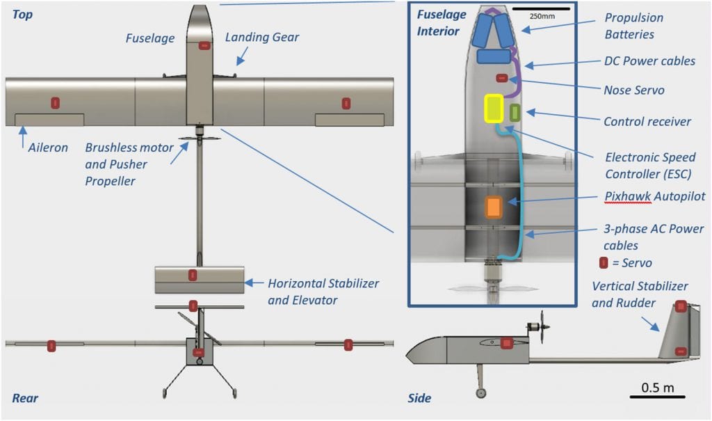
Component layout of the UAS. Servos are not drawn to scale.
Mapping the Magnetic Interference from a Fixed-Wing UAS
Furthermore, the outline of the method is for mapping the magnetic interference from a fixed-wing UAS to identify the problematic sources of noise and inform the magnetometer location.
“This method rests on two assumptions. The first assumption is that the interference will reach acceptable levels away from the UAS given enough distance from the magnetic sources. The second assumption is that, for survey operations, the magnetometer will ultimately be mounted on a boom attached to the UAS with consideration to minimize aerodynamic drag and boom length.”
The authors note an approach to best satisfy the considerations. They perform a survey including the magnetic mapping of the UAS – performed outdoors and with measurements using the geophysical instruments intended for the UAS during survey operations.
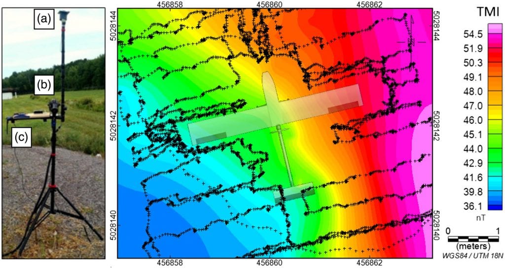
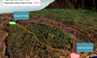
(Left) The test stand used for mapping mounted with (a) RTK GPS, (b) potassium total-field magnetometer, and (c) autopilot. (Right) Map of the diurnally-corrected background TMI. Crosses indicate the path of the test stand around the UAS during magnetic mapping with the motor engaged at 50% throttle (Fig. 10). Magnetometer measurements could not be made close to the running motor due to loss of lock, so the spatial sampling coverage is less dense on the starboard side of the UAS between the wing and the tail.
After carrying out two tests, the results show that the source of interference lied in the cables, especially when the motor was engaged. Therefore, they concluded that the motor must be “either removed or be engaged at a sufficient rotation speed” or to “be powered and the control surfaces oriented without deflection.”
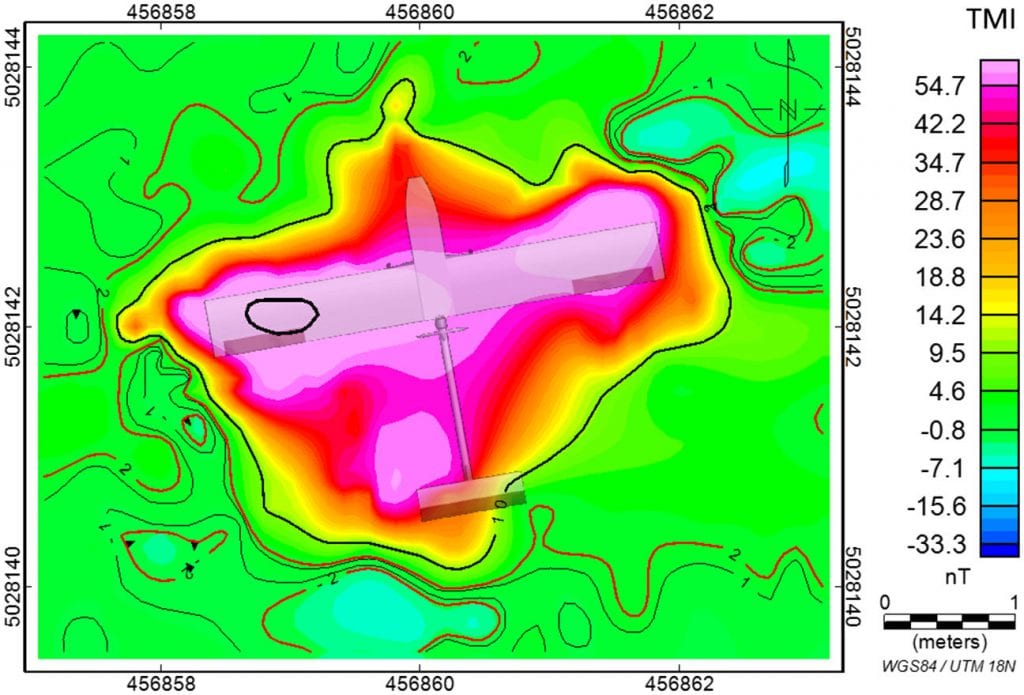
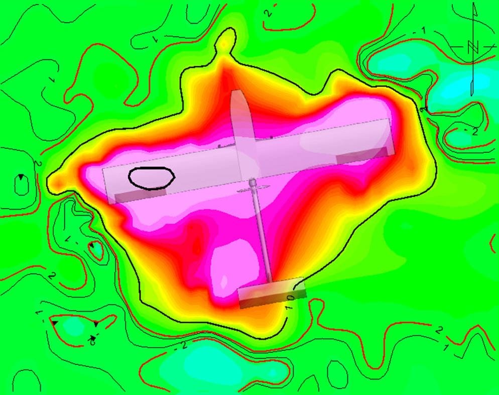
UAS magnetic anomaly map with the motor engaged at 50% throttle. Contours of ±1 (thin), ±2 (red), ±10, and ±100 nT (bold) overlay the grid.
Modifications for UAS and Similar Aircrafts
Based on this, the authors suggest a group of modifications for the UAS and similar aircraft, mainly in the organization of the DC battery cables, steel components, servos and wings – which should be all optimized in a unique way. They also noted that a compensation algorithm could be employed.
As an excerpt from the discussion section reads:
“Mapping around the propeller of the fixed-wing UAS required a fair berth so as not to risk contact between it and the test stand. Such risks would be greater with single and multi-rotor UASs because these UASs have larger, or multiple, areas of concern, which leaves few areas of interest to map. Alternatively, choosing a plane beneath the UAS could have adverse effects on the GPS while choosing a plane over the UAS would not be possible with the proposed test stand.”
Other future work, according to them, could include extending the proposed method which has been designed for a 2D planar canvas to a 3D one – which would obviously require greater efforts in terms of testing and mapping.
Citation: Magnetic interference testing method for an electric fixed-wing unmanned aircraft system (UAS), L. Tuck, C. Samson, J. Laliberté, M. Wells, F. Bélanger, Journal of Unmanned Vehicle Systems, 2018, 6:177-194, https://doi.org/10.1139/juvs-2018-0006